This is a page where I describe the creation of an Rf-using, Python-scripted, Raspberry Pi-and internet-enabled automatic -80C alarm for our Dow -80C freezers. .. .. .. and/or where you can find an answer the eternal question: How cold is cold? A: Ice Cold.
Our Project Components:
- 1 Raspberry Pi 2 Model B v 1.1 in a case running Raspbian Stretch Desktop (11/2017) Installed on an microSD card.
- 1 Ciseco SRF and Slice of Radio monitor (from Wireless Things – purchased from PrivateEyePi) and installed onto the RPi as a shield. Ciseco does not exist anymore.
- One monitor, one keyboard, and one mouse.
- 1 6AA battery case with 4x AA Energizer Ultimate Lithium batteries (~3000mAh) wired directly to a Ciseco SRF module on a PrivateEyePi board (per Freezer).
- Several Python 2.7 scripts edited from another freezer project found online (links to this project are now defunct, but it was originally posted by the Balfe lab at Univ. Birmingham around 2012).
- An internet connection and ethernet cord
- One or more (g)email email accounts.
- Any phone numbers you want to have the script text alerts.
- One or more twitter accounts (optional).
A Note before we begin. The project is made up of three main components:
- The Raspberry Pi (RPi) base unit with an attached “Slice of Radio” RF receiver shield – it uses a Ciseco SRF chip. This receiver acts as the ‘listener’ for temperature-value containing radio signals from the freezer(s) and interprets these signals to the RPi. As such, the SRF shield is in a ‘pass-through, serial’ mode as default behavior – this works for this project. The RPi in turn, runs the Python (2.7) script that interfaces with the RF listener and the internet/email/phone/twitter.
The below two components (2+3) are soldered together through wire leads from the battery case to the PWR and GND on the RF circuit board
2. The temperature sensor itself (a 10K NTCLE100E3103JB0 thermistor) soldered into a circuit board with a SRF chip – this chip acts as a ‘talker’ to the ‘listener’ that’s on the RPi once its firmware is updated (see step 6 below).
3. A 6xAA plastic battery case, where the power and ground wires have been re-soldered as described below so that the case functions as two sets of two batteries in parallel run in series (see step 5).
—
Step 1: Get your Raspberry Pi set up. Install the Raspbian operating system (we installed Raspbian Stretch Desktop in Feb. 2018) on your SD card, assembly your Pi into its case, attach a monitor, keyboard and mouse, and power it all up. There are myriad guides on how to do this online.
Step 2: Set up correct date/time on your Raspberry Pi OS. This will become important as we run the main temp. sensing Python script.
Step 3: Plug the Slice of Radio (the ‘listener’) into the Raspberry Pi via the headers so that it is seated on top of the board.
Step 4: Make sure that the RPi operating system is allowing this Slice of Radio to access the serial port and communicate with the RPi. The method by which this step is accomplished depends on the type of RPi you are using. For the RPi 2b, it was enough to fire up the terminal and type the following:
$sudo raspi-config
a screen will appear; click on “5. Interfacing Options” followed by “P6 Serial”. Answer NO to login shell accessible over serial and YES to serial port hardware enabled then OK and then FINISH. Next, reboot your RPi. After reboot type the following at the terminal:
$dmesg | grep tty
This will allow you to see if tty0 is associated with the console. tty0 should not be associated with the console – there should be no line that reads “console [tty0] enabled”.
Step 5: Install and use minicom to communicate with the Slice of Pi board. Type into the terminal the following:
$sudo apt-get install minicom
This command will install a small piece of software that allows access to the serial port; the software is called minicom. Minicom is very barebones, but useful for communicating with both the ‘listener’ Slice of Radio ‘base station’ that is attached directly to the RPi AND the ‘talking’ temperature-sensing SRF modules that are powered by batteries in the freezer. It is essential to communicate with these devices and minicom is a decent way to do just that. To start up minicom using the 9600 baud rate of the RF connection, type:
$minicom -b 9600 -o -D /dev/ttyAMA0
In the terminal window, the minicom screen will startup. Use the CTRL-A Z command to bring up the minicom command summary window, toggle ‘local echo ON’ (the E command) and ‘Add linefeed’ (the A command) by typing in those letters. Next, open a text file and type
+++
into the text file. Copy these three additional symbols and paste them into the window of minicom. This command (‘+++’) is equivalent to a “HELLO” for the base station Slice of Radio. If the Slice of Radio is properly seated on RPi AND tty0 has been properly kept off console, the text “OK” should pop up next to the +++ that you paste in the minicom window – this means that the Slice of Radio is working and able to communicate via tty0. At this point, you can “listen” to the temperature via the Slice of Radio and Raspberry Pi – Hooray.
Step 6: Wire/solder/prepare the battery pack. Ideally, the design was for a ~3V power supply – Energizer Ultimate Lithium AA batteries are ~3000mAh (C/D would be more mAh, but we built what we built). Because of the finite mAh and the hypothesized negative effects of -80C temperature on battery life, we created a series of two 3V 2xAA batteries as follows:
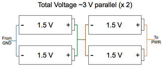
Following the above, we modified and re-soldered battery connectors in the 6xAA battery pack as follows:
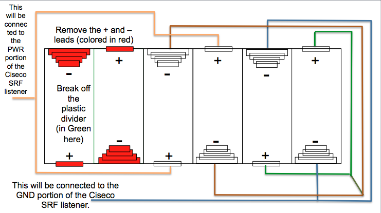
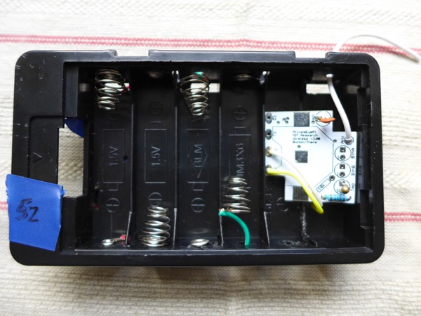
In real life, this (after covering up soldered junctions with electrical tape, ripping out the plastic divider in the final bay and attaching the Ciseco Wireless RF/temp board, the case looked as follows:
Step 7: Wire/solder/prepare the PrivateEyePi Board to the Thermistor/Resistor/Capacitor/Power leads. The instructions are found here. NOTE: Only one resistor is necessary, the coin cell does not need to be attached. ALSO NOTE: BEFORE the – wire from the above battery box is soldered to the GND pad of the board and the + wire is soldered to the 3.3V pad on the board…the firmware on this board needs to be updated. Because the ‘talker’/thermistor chip is exactly the same as the chip used for Ciseco’s XRF projects, a firmware updater tool created by Ciseco could be installed on the RPi and used as a software updater. This firmware updater software required a binary file, also available on Ciseco’s Github, as the actual new firmware.
A (potentially helpful?) aside: the chip and thermistor work together as follows – temperature is sensed as a particular voltage by the thermistor and then relayed in the LLAP language, via the chip and RF, to the “Slice of Radio” listening device. The original personality of the “Slice of Radio”/SRF “listener” was as a serial pass-through device – it acts just like that sounds, as a pass-through of the data collected from “talker” RF devices communicating at a particular baud. So, nothing needed to be changed about the “Slice of Radio” for it to work for this project. The original personality of the “talker” wireless things temperature sensor/SRF board was a “Temperature/Thermistor” personality. When this chip with this personality was put in a -80C freezer, the LLAP message received was an error message (aXXTMPA-0273). This error message only occurred when the temperature dropped below 55C, and was assumed to be a problem with the firmware on the chip calculating temperature from voltage (the method of calculation perhaps used an equation that was not valid at such a low temperature). Monkeying around with the LLAP commands that change the B coefficient of the Steinhart equation (BVAL) and thermistor resistance at 25C (RNOM) yielded no change in the error message. Changing either the analog input resistance (IR) value or the series resistor value (SRES) yielded temperature sensing down to -80C, but the readings were not stable at all (fluctuations of at least 10 degrees centrigrade were common with the freezer door closed).
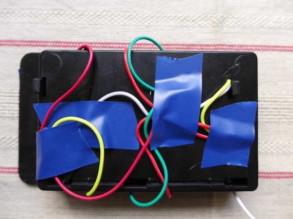
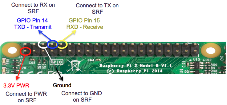
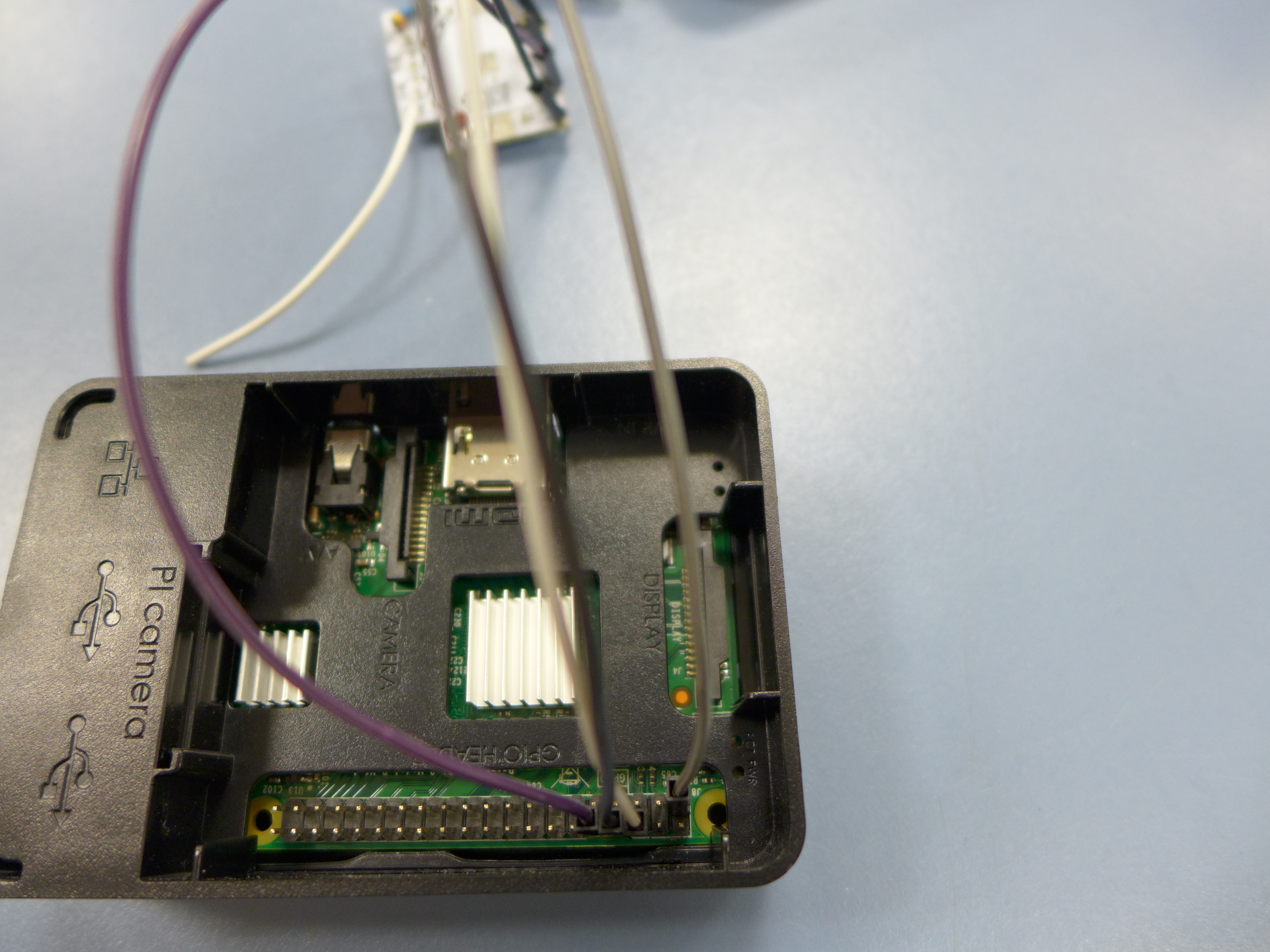
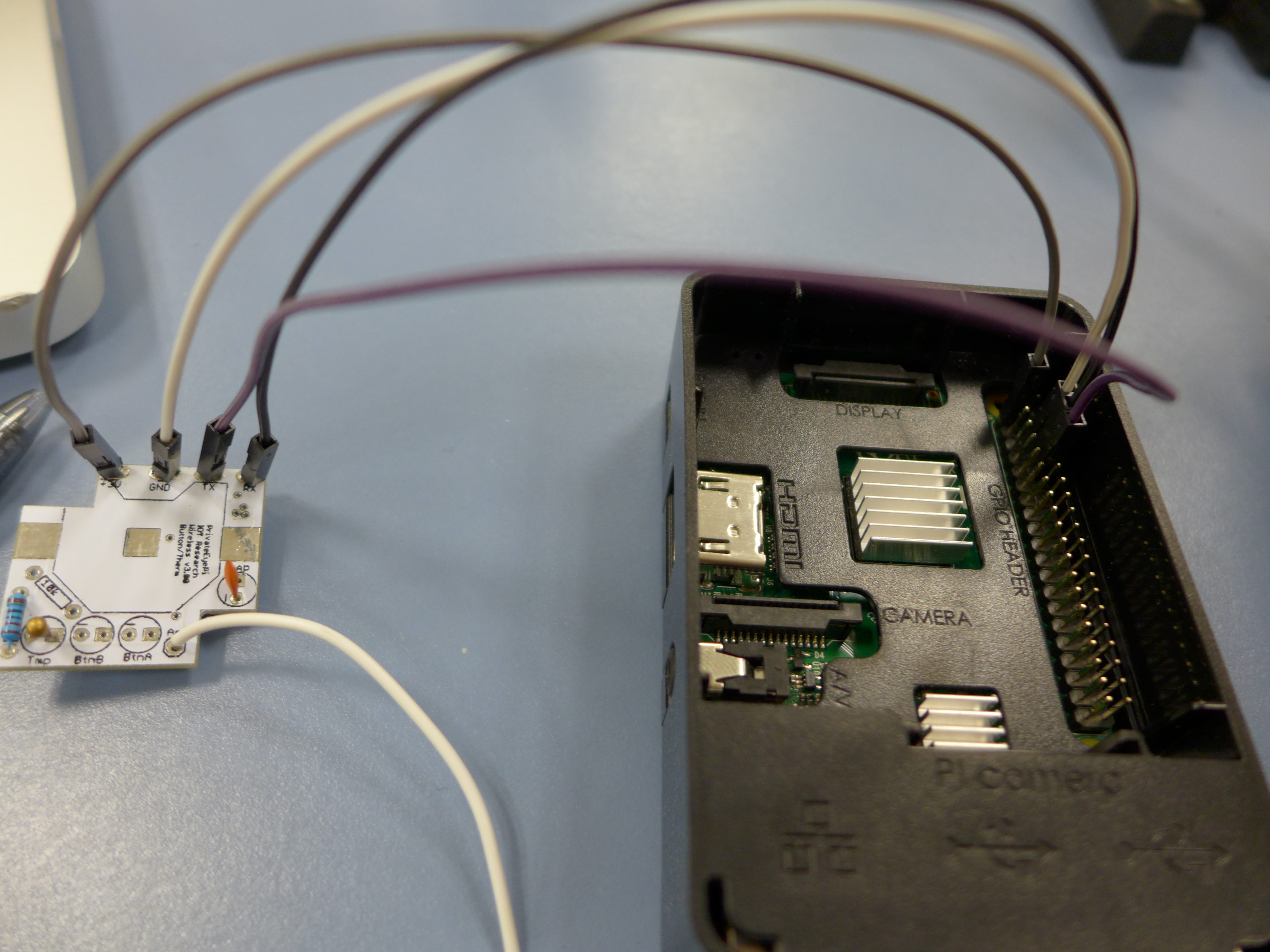
In order to update the firmware on the SRF/Thermistor board, individual jumpers were soldered into the “PWR”, “GND”, “RX” and “TX” ports on the board.

These jumpers were then connected to particular pins on the RPi’s board (after the Slice of Radio shield was removed) as per the photos below:
After the cables were connected, the RPi was plugged in and software for the firmware update was downloaded. The firmware loader is here on github, but the .cpp file is here as well (as a .pdf). The firmware itself can be found here on github, and the single binary used to update this project was named “llapAnalog-V0.77-24MHz.bin”. The commands (via Terminal) used to compile the .xrf_uploader and upload the firmware via the RPi were as follows:
$ g++ xrf_uploader.cpp -o xrf_uploader
$ chmod +x xrf_uploader
$ ./xrf_uploader -d /dev/ttyAMA0 -f llapAnalog-V0.77-24MHz.bin
Writing new firmware file llapAnalog-V0.77-24MHz.bin to device /dev/ttyAMA0 with baud rate 9600...
Reading firmware file...
Read 1242 lines from firmware file
Opening device...
Setting serial parameters...
Waiting for device to settle...

<> Entering command modus
<- OK
-> ATVR
<- 0.60B APTHERM
<- OK
-> ATPG
<- OK
<> Sent 1242 of 1242 lines...

All OK, XRF successfully reprogrammed!

Waiting for device to settle...

<> Entering command modus
Timeout, no data received within 10 seconds
For some reason, the “no data received” was returned (most likely because the device was not programmed to “talk” its voltage by default. The jumpers were removed from the RPi and from the SRF/thermistor board and the GND and PWR ports on the board were soldered to the battery leads in the case. The Slice of Radio shield was re-connected to the RPi.
Step 8: Attempt to “listen” to the temperature over RF via the RPi. To do so, type in this command to the terminal:
$minicom -b 9600 -o -D /dev/ttyAMA0
Minicom will start up, the output from the screen should look something like this
Welcome to minicom 2.6.1

Options...
Compiled on ...
Port /dev/tty01

Press CTRL-A Z for help on special keys
Use CTRL-A Z to toggle a menu where you can add echo and line wrapping to the screen output. Put batteries in the battery holder. If everything is wired together properly, the following should show up on the minicom terminal window.
a--STARTUP--a--STARTUP--a--STARTUP
This tells you that the device currently has no DEVID (the “a–” part of the message) and has started up. To double-check that the device can “hear” you via the minicom terminal, type “a–HELLO—-” into a text editor, copy, and paste to the terminal/minicom window. You should immediately get an identical response from the SRF/thermistor as it talks to the Slice of Radio and RPi/terminal – the window should look something like this.
a--HELLO----a--HELLO
At this stage, you want to give each device a unique DEVID and change the frequency with which it turns on and “talks” its voltage (temperature).
To program a unique DEVID:
type “a–CHDEVIDXX” (where “XX” is the new device ID name – can be alphanumeric) into a text editor, copy, and paste to the terminal/minicom window. In the terminal/minicom window, this command should be repeated back.
type “a–REBOOT—” into a text editor, copy, and paste to the terminal/minicom window. This will reboot the device. In the terminal/minicom window, this command should be repeated back followed by the following several lines, indicating the chip has rebooted.
aXXSTARTED--
aXXSTARTED--
aXXSTARTED--
aXXSTARTED--
aXXSTARTED--
The device should now have a changed ID (“XX” in the above should indicate this new ID). You can use the HELLO command above (with correct ID) to test this if you are so moved.
To program in the frequency at which the device turns on and talks its voltage:
type “aXXINTVL060S” into a text editor, copy, and paste to the terminal/minicom window. This will instruct the device to talk its voltage temp once a minute, every minute. The minicom will “listen” as the SRF chip “talks” and should output something like the below to the terminal.
aXXANA1989--
Again, in the above “XX” is the device ID. “ANA” means analog mode?, maybe? The final number is the value for the thermistor’s voltage at the current thermistor/SRF chip/battery case temperature. If you really love LLAP (the language you’ve been using in minicom to program the SRF, I’ve done a wayback machine grab of the main bits in the linked content here: XRFFirmwareLLAP_TempThermistor.
Step 9: Gather temperature data from the RF via the RPi and construct a polynomial curve.
From here, assuming things are copacetic, you would proceed with using your working SRF/thermistor to measure temperatures at room temperature, 4C, -20C, -80C and as many temperatures between -20C and -80C as you have reliable access to…There’s a bit of a trick here, in that you have to have some other way of monitoring exactly what a given low temperature is while making your SRF reading – this doesn’t tend to be a problem with -80C freezers, which have a visual output of temperature.

For our lab, we have two -80C freezers. We made a temperature graph for each here

As you can see, there’s no data above -50C – and even with the included, it is difficult to draw a best-fit curve. Clearly these thermistors, at -80C, are nearing their usable limits. Still, a linear relationship can be used for the three lowest temperatures, and was, giving us equations for lines of best fit.
After gathering such data for your SRF/thermistor pair(s), we can move on to turning the SRFs on cyclically for freezer use.
Step 10: Reset the temperature interval and turn the SRF wake/sleep cycling “on.”
NOTE: turning cycling on makes it very difficult to communicate with the SRF. In fact, impossible for a human. The Balfe lab created a python script to do this communication, and we’ll a .pdf of that script here: setCycle.py.
OK, so you are committed, correct?
Assuming minicom is still open, type “aXXINTVL060M” into a text editor, copy, and paste to the terminal/minicom window. This will instruct the device to talk its voltage temp once an hour, every hour. The minicom will “listen” as the SRF chip “talks” and should output something like the below to the terminal, yadda yadda, just like before.
aXXANA1989--
Now, the cycle part. Type “aXXCYCLE—-” into a text editor, copy, and paste to the terminal/minicom window. This will instruct the device to turn on only when making a temperature reading [and taking additional time to communicate that reading to any listening device(s)]. The terminal should show the following message – demonstrating the device is now cycling (and has gone to sleep).
aXXSLEEPING-
That’s it. Now you’re locked in and set – the device will read temperature as voltage and “talk” via RF to any listening devices once an hour, every hour. There is one thing to note – every 10th “reading” will actually be a battery report by the device and not a voltage. At each battery reading, it is possible to communicate with the device and interrupt its cycle – this is effectively what the above Balfe lab script is doing.
Close minicom (CNTRL-A and X), you’re now done with minicom.
Step 11: Edit and Run a python script that will check temps, tweet, SMS, and email if things go warm.
This script is long, and at parts, complicated. But there are really only a few different set-up variables that you should pay attention to and tweak. Many are obvious and commented in first thirty lines of the script (gmail and twitter account details, reporting preferences, etc.). We went the direction of signing up for freezer twitter and gmail accounts, and then allowing the gmail account to SMS text cell phones if the alarm email was sent. (this is something you can do via simple filtered forwarding – see the entry from K. Favilla here: FWDGmailAsText_KFavilla).
Before the script runs, you’ll need to do the matplotlib installations that are listed at its beginning.
Finally, you’ll need to tweak your device IDs and also linear equations for voltage -> temperature conversion, as well as alarm temperature conditions. Double finally, you’ll need to add some account information.
Good luck! and here’s that final script with all important account details ready to be filled in: Chatterbox7_NoVar.py